 bancika
12 KiB
System requirements
- Java JRE/JDK 1.6.0_45-b06 or newer
- 1GB free RAM memory is recommended
- 10MB free hard drive space
- Zip utility to unpack the archive (7-zip, WinZip, Total Commander, etc)
Running the app
For starters, make sure that you have downloaded the correct version. Mac OSX builds have names that end with "osx". The build without "osx" in their name are multi-platform and will work pretty much anywhere provided that Java JRE is available for that platform.
-
On Windows just run the diylc.exe
-
On Linux/Unix (will also work on Mac OSX if not using the OSX dedicated build), open the terminal, change the directory to diylc3 (cd
<path to diylc3>) and type ./run.sh -
On Mac OSX you will need to allow 3rd party apps and then run the application package.
User interface
User interface can be separated into 4 major components:
- Canvas is used as a WYSIWYG editor for the project.
- Component tree (or toolbar) lists all available components and allows you to pick the one you want to add.
- Main menu offers file operations, such as saving, loading and exporting, clipboard operations, etc.
- Status bar: shows context related information, zoom control, update information and memory consumption.
Configuring the application
Application configuration may be changed from Config menu. It contains the following items:
- Anti-Aliasing: when checked, objects and text will look smoother but it takes more time to render anti-aliased graphics. If you suffer from performance issues, try turning this option off.
- Auto-Create Pads: when checked, application will automatically create solder pads whenever a component is added to the layout.
- Auto-Edit Mode: when checked, the component edit dialog will appear after each component is created, the same way version 1.x works.
- Continuous Creation: when checked, the last selected component type will remain active after you create a component, allowing you to create many components of the same type rapidly.
- Show Rulers: controls whether the rulers should be displayed
- Show Grid: controls whether the grid lines should be shown while working on the project.
- Export Grid: controls whether the grid lines should be exported when saving the project to a file or printer.
- Hi-Quality Rendering: when checked, image quality will improve slightly, but it may decrease performance.
- Mouse Wheel Zoom: when checked, mouse wheel zooms in and out instead of scrolling the visible area of the project.
- Outline Mode: when checked, components are drawn only as the the outline with no fill color or decorations.
- Snap to Grid: when checked, drag & drop operations will snap control points to the grid instead of following the mouse cursor pixel by pixel.
- Sticky Points: when checked, components are allowed to stick to each other when moved. Hold Ctrl key while dragging to temporarily toggle the Sticky Point mode. See Control points for more info on control points.
- Theme: allows selecting a theme. Themes are read from themes directory under the DIYLC root and they include background color and grid line color. You can create your own themes by adding an XML file to themes directory. It's easiest to start with a copy of one of the existing files.
Adding components to the project
This sections explains how to add an existing component to the project. To learn how to develop your own components follow this tutorial. To instantiate a component, follow these steps:
- Locate the component in the toolbox. Components are categorized into several folders, so make sure you're looking into the right one. To speed up the process, search box at the top of the component tree can be used to narrow down the list of displayed component types.
- Click on the desired component type. Note that text in the status bar changes to reflect this action.
- Click on the desired location on the canvas to create the component. Some components (solder pads, trace cuts, etc) will be created on single click, others (like resistors, jumpers, etc) will require two clicks to set both ending points. Instructions in the status bar will guide you through the process. Component will be drawn translucent until the creation process is finalized.
Moving components
The easiest way to move a component across the canvas is to drag it by clicking on it's body and moving the mouse to the desired location. When mouse cursor is over a component, it will change to "hand pointer" and status bar will read name of the component that will be dragged.
Note that:
- if more than one component is selected, all of them will be moved
- moving one (or more) components will move/stretch any components that are stuck to them. Status bar will inform you which components will be affected. Hold Ctrl to unstuck the selected components and move them only.
Control points
A component may have one or more control points. Control points determine component's position on the layout and in some cases allows the component to get connected with other components. For some components, such as resistors, wires, etc, individual control points can be moved around when the component is selected.
Note that:
- status bar lists all the components that will be affected by the drag&drop operation.
- you can drag control points only when they turn green.
Editing component properties
Newly added components are assigned with default parameters (size, color, value, name, etc), but it is possible to edit them in a few different ways. The simples way to edit properties of a single component is to double click on the component. Another way to do it is to select "Edit Selection" from the context menu aciton or press "Ctrl + E" on the keyboard. The second approach also allows editing multiple components at the same. When editing multiple components at the same time, only properties common for all the selected properties will be shown. If we, for example, want to edit a resistor and a capacitor at the same time, we will not be able to edit capacitance or resistance because they apply on to one of the selected components. Input boxes that represent properties that have mixed values are highlighted in yellow to designate that we cannot see all values from the selection. Changing a value in the yellowed box will appply it to all the selected components.
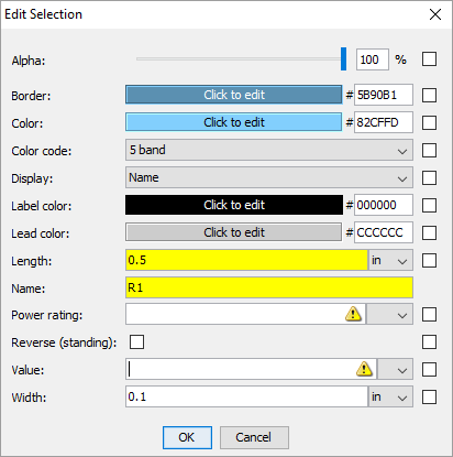
Checking the "Default" checkbox on the right side will make the value for that property a default for the component. In other words, all the components created after that will inherit that value instead of the factory default value.

Input boxes that represent measures (size, resistance, capacitance, etc) can take math expressions in addition to constants. For instance you can type 3/32 and it will be automatically converted to decimal. Even more complicated expressions with parenthesis and 4 basic numerical operators are possible.
Using component variants
Each component is created using default values for size, color, etc. Users can make their own variants of components with different properties. After the component is edited to the desired state, it can be saved as a variant using the context menu action.
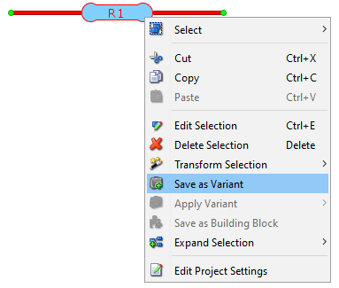
After saving, the existing component variants can be employed in few different ways. One way would be to apply the variant to the existing component by using the context menu.
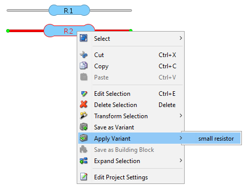
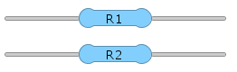
Applying a variant will copy all the properties associated with the variant to the selected component and transform it to conform the variant.
Another way to use variants is to add a component to the project using a saved variant as a blueprint. This can be done by right clicking on a component icon in the component tree and selecting a desired variant from the context menu.
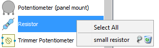
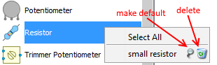
Furthermore, a variant can be set as default and all components created after that will inherit their properties from the default variant. That can be done by using the pin button in the aforementioned context menu. Next to the pin button is the delete button we can use to delete a variant.
Grouping components together
Component grouping works similarly to the way object grouping works in most vector-based drawing tool. The idea is to keep two or more components together and move/edit/delete them at the same time. To group components, select them and press Ctrl+G (or select "Group Selection" from the menu). Double click on one of the grouped components will open the editor with all the mutual properties of selected components and allow editing them at the same time. Note that while the components are grouped, you cannot edit drag their individual control points. To un-group the components, select them and press Ctrl+U (or select "Ungroup Selection" from the menu).
Note that:
- nested groups are not currently supported. If you group two groups of components together you'll end up with one large group instead of a group that contains two groups.
Using building blocks
Often times we use a cluster of components arranged and configured in a certain way repetitively. To speed up the process, DIYLC allows for a group of components to be saved as a building block and recalled simply by one click. This saves time needed to add each individual component and configure it to look the way we want. Suppose we want to make a leaded TO92 component. DIYLC provides enough pieces to build one. We can add a folded TO92 body together with three separate wires.
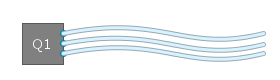
To save this as a building block that we can use later, we need to select all four components and select "Save as Building Block" action from the context menu
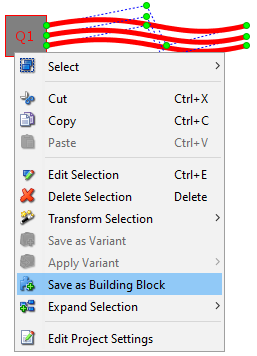
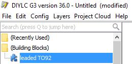
The newly created building block appears immediately under "(Building Blocks)" folder in the component tree and can be used just like any other component.
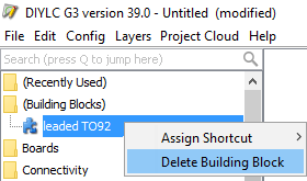
To delete an existing building block, use the context menu action.
Using the status bar
Status bar contains three different features:
- Information bar shows context related information and guidance through the app.
- Selection size shows the dimensions of the minimal bounding rectangle that contains all the selected components. It takes default size units (in or cm) into account.
- Zoom control allows you to zoom in or out.
- Announcements shows public announcements if there are any posted.
- Auto-update notification. When the bulb is on, there are updates available. Click on it for more information.
- Memory bar is the blue-ish icon on the right side that shows the amount of memory occupied by the application. Move the mouse over it to see more details or click on it to try to cleanup as much memory as possible. Color will turn red when memory consumption is running high.